 FREE 1 to 3-Day Delivery on Orders $149+ Details

How to Install Crown Automotive In-Steering Column Directional Switch (94-95 Jeep Wrangler YJ) on your Jeep Wrangler
Installation Time
5 hours
Tools Required
- 1⁄2 in Socket (for battery terminal)
- 13/16 in Socket (main Steering Wheel Retaining Nut)
- 3/4 in Socket (Steering Column support bolts)
- Socket Wrench
- Torque Wrench
- Phillips Head Screw Driver
- Two Flat Head Screwdrivers
- Steering Wheel Puller
- Lock Plate Compressor
- Crown Automotive In-Steering Column Directional Switch
- Guide Strap
- Tape

Shop Parts in this Guide
Installation Notes, Pre-Installation notes: This installation is on a 1995 Jeep Wrangler YJ with a 2.5-inch lift. This should be similar for all Wranglers in the YJ line (1987-1995).
Installation Instructions:
1. Prepare car: Park on a level ground. Make sure the wheels are as straight as possible.
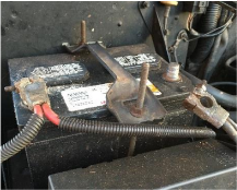
2. Disconnect cable to negative post on the battery. Mine is connected with 1⁄2 in head bolt.
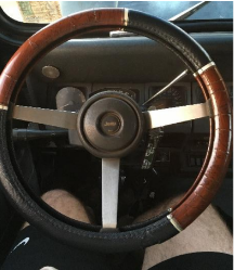
3. Remove horn pad. This simply pops off.
4. Remove Bushing and Receiver. These are held in place three Phillips head screws.
5. Remove flex-plate and insulator. The insulator is held to the steering wheel with three Phillips head screws.
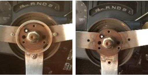
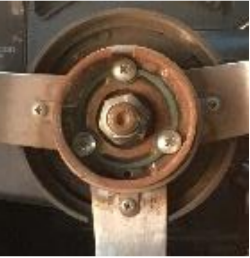
6. Remove the horn contact and spring (note order: spring deepest, pen, retaining ring holds pen in place).
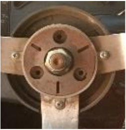
7. Remove steering wheel retaining nut with 5/8 socket. Mark center bolt and steering wheel with a mark for alignment during reassembly.
8. Bolt a steering wheel puller to the steering wheel. Many chain auto parts stores have pullers as part of their tool loan program. Tighten the center bolt on the puller and the steering wheel will come loose.
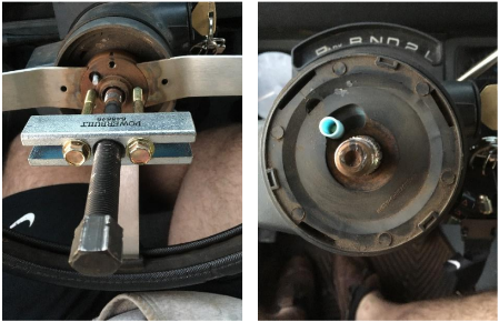
9. Use flat head screw driver to pop lock plate cover off. Gentle outward pressure at each of the slits will move the cover off.
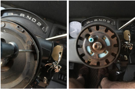
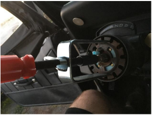
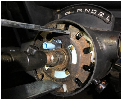
10. Attach a compression tool on the center bolt and tighten to compress the locking plate away from the retaining clip. The official service manual strongly advises to not try and remove the retention clip without using a compression tool.
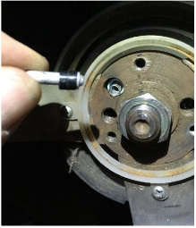
11. Use a pick or couple of small screwdrivers to move the retaining clip up on the center bolt. Remove the compressor and then the retaining clip.
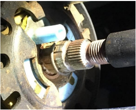
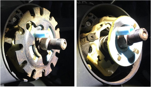
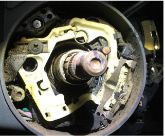
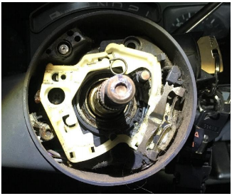
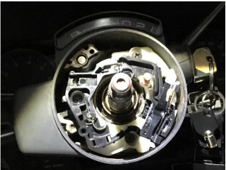
12. Remove the lock plate, cancelling cam, preload spring, and thrust washer.
13. Remove the three Philips head screws that hold the turn switch module in place. You will need to move the turn signal to access one of the screws.
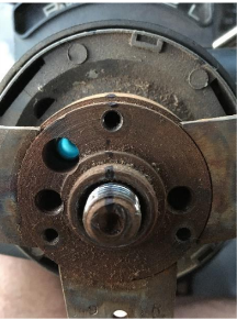
14. Remove the turn signal switch retaining screw. This will release a linkage between the turn switch module and the turn signal arm.
15. Remove the hazard-warning switch. It is held in place with one Phillips head screw.
16. Unclip the Turn Signal switch wiring harness at the base of the steering column. You may tape the wiring harness or cut the wires to ease removal. (I opted for cutting wires.)
17. Attach a guide strap to the wires. Remove the turn signal switch and gently pull the wires and guide strap up through the steering column. (The guide strap is a recommendation based on my mistake and then spending three hours trying to fish the new harness down the column.)
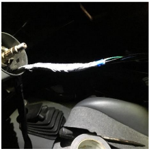
18. Tape the guide strap to the new harness. Use the strap to pull the new harness and wires down the steering column.
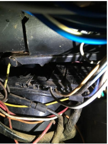
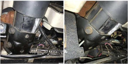
19. [Optional] You may need to remove the lower dash panel and loosen the support bolts at the base of the steering column and push up on the steering column to provide the give enough clearance for the harness. (3/4 in socket). The wires should be pass the support bracket behind a padded conduit. The photos below show mine missing the conduit to the passenger side.
20. Reattach the three screws that hold the turn signal switch in place. I had to rotate the switch to access one of the screws.
21. Clip new wiring harness into place. It is possible to access this plug from below, but removing the lower dash panel gives easier access.
22. Replace the lower dash panel and all replace all support bolts at the base of the steering column.
23. Replace the turn signal linkage and retaining screw. I found it easiest to align the linkage with the directional switch rotated clockwise (right turn) and with the turn signal arm in the up position. Checked that linkage is in place and the turn signal arm correctly rotates the directional switch.
24. Replace thrust washer, preload spring, cancelling cam and locking plate.
25. Place retaining clip on center bolt. Use lockplate compressor to compress lockplate below recess for retaining clip. Push retaining clip into place using a couple of flat head screwdrivers.
26. Replace lock plate cover and steering wheel. Be sure to align steering wheel using the alignment mark made earlier. Gently place steering wheel onto center column.
27. Use only the retaining nut to force the steering wheel into place. Tighten the retaining nut to 25 ft – lbs (34 N-m)
28. Replace horn components: Horn contact (spring, pen and retaining ring), insulator, flex plate, receiver, bushing, horn pad.
29. Reconnect battery.
30. Check horn and turn signals. Reset radio and clock.
Installation Instructions written by W.D. McRae, 11/25/2018

