FREE 1 to 3-Day Delivery on Orders $149+ Details

How to Install Auto Meter Direct Fit Dash Gauge Panel (97-06 Wrangler TJ) on your Jeep Wrangler

Shop Parts in this Guide
Read instruction thoroughly to verify all required parts are there before installing this product.
CAUTION FOR ALL GAUGE INSTALLATION
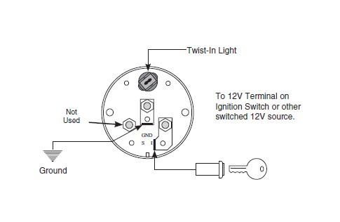
As a safety precaution, the 12V wire attached to the positive I ( ) terminal of the gauge should be fused before connecting to the positive ( ) output side of the ignition switch. We recommend using a 4 Amp, 3 AG fast-acting type cartridge fuse (Littlefuse® # 312 004 or an equivalent) inline between the power supply source and the I ( ) terminal on the gauge.
NOTE: Some late model vehicles use electronic sensors in their pressure and temperature senders for engine control functions. Before removing the original sender, we recommend that you contact your automotive dealer to be sure no critical functions will be disrupted. With pressure gauges it is beneficial to add a T-fitting to install your new gauge and to keep the warning light operational. This allows you to monitor the pressure and still have a warning light to indicate emergency conditions.
NOTE: Disconnect negative (-) battery cable before installation.
CAUTION: Do not touch ignition wire to the sender (S) terminal on back of gauge or the sender may be damaged.
Mounting
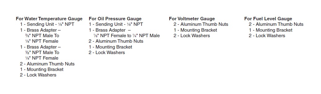
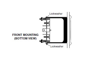
These gauges can be mounted in-dash or in Mopar mounting solutions (panels, cups, pods, etc.). 21⁄16” diameter gauges mount in 21⁄16” hole, 25⁄8” diameter gauges mount in 25⁄8” hole. Fasten with brackets supplied as shown. (Hookup wire is required.) To assure proper functioning of this instrument, please read instructions thoroughly before installing.
Metric Adapters
If this product is to be installed on a vehicle requiring metric fittings, please contact you local Mopar dealer to purchase metric adapters.
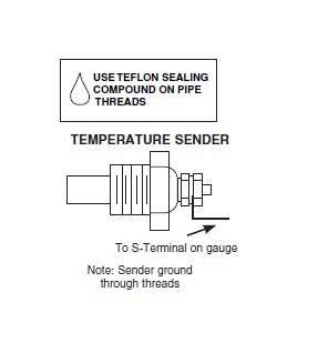
Temperature Gauges
1. Install temperature sender.
A. Water Temp: Install temperature sender (included). Purchase of additional fittings such as metric or hose adapters may be required.
B. Oil & Trans. Temp: Hole may have to be drilled and adapter nut (included) welded or brazed in pan. Be sure there is adequate internal clearance for nut and sender. Sender should automatically be grounded when installed. If not, proper ground connections should be made. May use #2260 weld on bung on steel pans (not included).
C. Cylinder Head Temp: Head must be drilled and tapped for 1⁄8” NPT hole. Sender should be grounded automatically when installed. If not, proper ground connections should be made. Be sure not to drill all the way through.
D. Axle/Diff. Temp: Install temperature sender in 1⁄8” NPT sender port on cover if available. If cover does not have a port, remove cover and drill and tap a 1⁄8” NPT hole or, drill and weld, or braze, adapter nut (included) in cover. Proper ground connections should be made by running ground wire from bolt in cover to chassis, being sure to leave enough slack in wire for suspension travel.
E. Transfer Case Temp: Determine suitable location on side of transfer case to drill/tap for 1/8” NPT sender. Ensure location is below fill plug and below full line of fluid level.
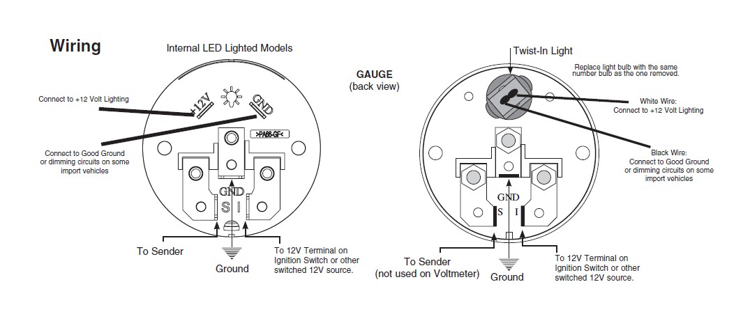
2. Route 18-gage wire through firewall. If a new hole is drilled in the firewall a grommet is recommended. Connect one end to terminal post on temperature sender, and opposite end to sender (S) terminal on back of gauge.
3. Route 18-gage wire from center terminal GND (-) on back of gauge to good ground near sender.
4. Connect wire from ignition switch to ignition ( I ) terminal on back of gauge.
5. Reconnect negative (-) battery cable.
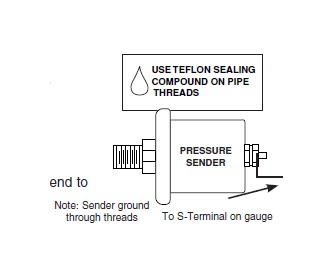
Pressure Gauges
1. Install sender into pressure port of appropriate type. If unit is to be installed on a high vibration application such as a full race engine or engine capable of high RPM, it is strongly recommended that the sender be remote mounted to either the fenderwell or firewall, to insulate from vibration. Failure to remote-locate pressure senders on such an application could result in gauge failure and potential damage to vehicle and/or operator injury. Braided stainless steel lines are, recommended to accomplish this. Sender features 1⁄8” NPT male fitting and comes with 1⁄4” NPT adapter. Sender should automatically be grounded when installed. If not, or if remote relocation of sender is required, a ground connection to sender “body” may need to be made.
2. Route 18-gage wire through firewall. If a new hole is drilled in the firewall a grommet is recommended. Connect one end to terminal post on pressure sender, and opposite end to sender (S) terminal on back of gauge.
3. Connect wire from center terminal GND (-) on back of gauge to good engine ground near sender.
4. Connect wire from ignition switch to ignition ( I ) terminal on back of gauge.
5. Reconnect negative (-) battery cable.
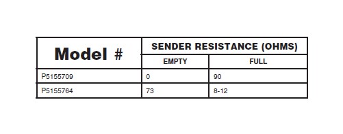
Fuel Level
Contact Mopar Technical Support if help is needed in determining your sender resistance.
Note: Before beginning installation, check to make sure stated resistance for gauge (listed on box) matches your sending unit value for proper operation.
NOTE: Failure to ground sender as in step 5 may result in inoperable gauge.
1. Gauge connects to fuel sender on fuel tank. Existing wires may be used, or route proper length of 18 gage wire from fuel tank to gauge. If a new hole is drilled in the firewall a grommet is recommended. Connect one end to terminal post on fuel level sender and the opposite end to the sender (S) terminal spade on back of gauge.
2. Connect ground wire from ground post on gauge to suitable chassis ground.
3. Connect wire from ignition switch to the positive I ( ) terminal on the back of gauge.
4. Reconnect negative (-) battery cable.
5. Be sure that body or mounting flange of sender is grounded to suitable chassis ground.
Voltmeter
1. Using 18 gage wire, route one length through firewall. If a new hole is drilled in the firewall a grommet is recommended. Attach one end to the negative GND (-) spade terminal on back of gauge, and the opposite end to a good engine ground. See illustration at right.
2. Attach one length of wire to the positive I ( ) terminal on back of gauge and opposite end to 12V terminal on ignition switch or other 12V power source.
3. Reconnect negative (-) battery cable.