 FREE 1 to 3-Day Delivery on Orders $149+ Details

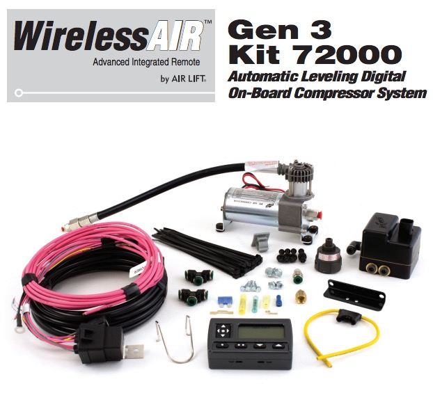
How to Install an Air Lift Wireless On Board Air System on your 97-18 Jeep Wrangler TJ, JK & JL
INSTALLATION GUIDE
For maximum effectiveness and safety, please read these instructions completely before proceeding with installation.
Failure to read these instructions can result in an incorrect installation.
Introduction
The purpose of this publication is to assist with the installation, maintenance and troubleshooting of the WirelessAIR System.
It is important to read and understand the entire installation guide before beginning installation or performing any maintenance, service or repair. The information here includes a hardware list, step-by-step installation information, safety information and a troubleshooting guide.
Air Lift Company reserves the right to make changes and improvements to its products and publications at any time. Contact Air Lift Company at (800) 248-0892 for the latest version of this manual.
SYSTEM INFORMATION
WirelessAIR is designed for automatic digital leveling of the on-board compressor system. The kit includes a compressor, manifold, wiring harness, and wireless digital controller. The system can be used in or outside the vehicle, for adjustments in full view of the vehicle.
The wireless digital controller is a compact, battery powered unit. It also includes a clip that can be attached to the vehicle’s visor. Three user-defined memory settings are provided for frequently used settings. As an added safety measure, minimum air pressures are automatically maintained. The manifold is also weather resistant for maximum life expectancy.
IMPORTANT SAFETY NOTICE
The installation of this kit does not alter the Gross Vehicle Weight Rating (GVWR) or payload of the vehicle. Check your vehicle’s owner’s manual and do not exceed the maximum load listed for your vehicle.
Gross Vehicle Weight Rating: The maximum allowable weight of the fully loaded vehicle (including passengers and cargo). This number — along with other weight limits, as well as tire, rim size and inflation pressure data — is shown on the vehicle’s Safety Compliance Certification Label.
Payload: The combined, maximum allowable weight of cargo and passengers that the truck is designed to carry. Payload is GVWR minus the Base Curb Weight.
Hardware and Tools Lists
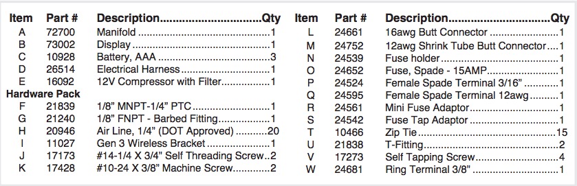
HARDWARE LIST
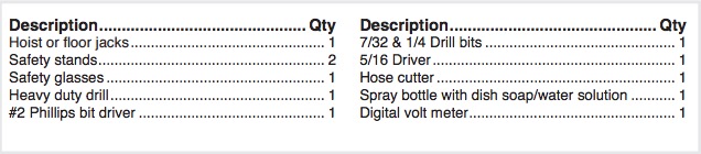
TOOLS LIST
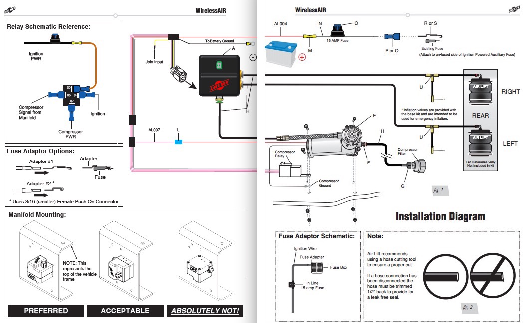
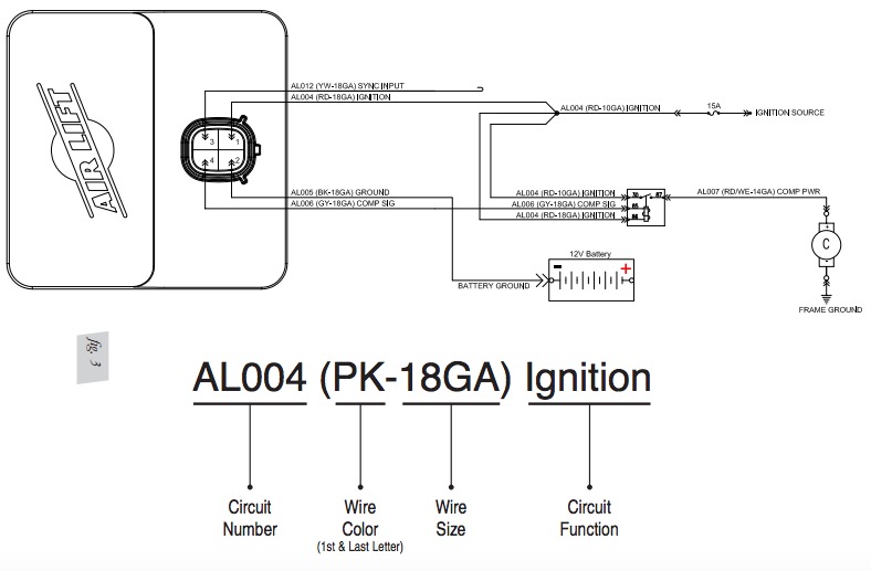
Installation - Electrical Schematic
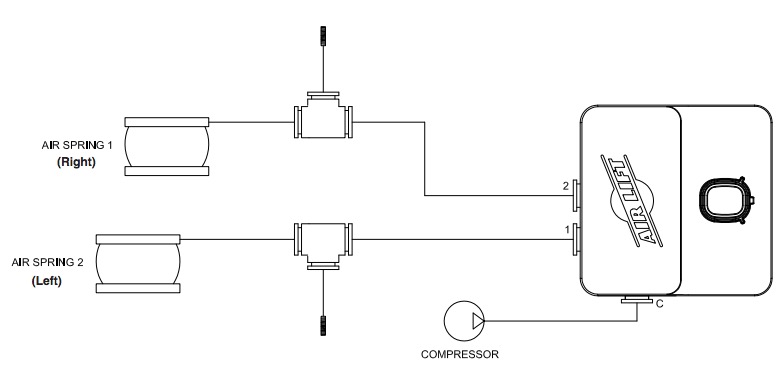
Installation - Pneumatic Schematic
Installing the WirelessAIR System
RECOMMENDED COMPRESSOR LOCATIONS
Important
LOCATE COMPRESSOR IN DRY, PROTECTED AREA ON VEHICLE. DIRECT SPLASH OR EXCESSIVE MOISTURE CAN DAMAGE THE COMPRESSOR AND CAUSE SYSTEM FAILURE.
Disclaimer: If you choose to mount the compressor outside the vehicle please keep in mind the compressor body must be shielded from direct splash and the intake should be snorkeled inside the vehicle. If the compressor does not include a remote mount air filter or if mounting the compressor outside the vehicle, make sure to orient the compressor intake filter so that all moisture can easily drain.
Please also remember...
• To avoid high heat environments (including engine bay and exhaust)
• The compressor can be mounted in any position — vertical, upside down, sideways, etc.
• Compressors ingest moisture and will deposit water inside the system. In sub 0˚F environments this water may freeze and require the addition of air brake antifreeze (see page 18).
INSTALLING THE COMPRESSOR
1. Select a rigid mounting location for the compressor on the vehicles frame or cross member (fig. 1) that shields the compressor from the elements and heat sources.
NOTE: The electrical harness will force the compressor to be within 24” of the manifold in order to make electrical connections.
2. Use the supplied compressor fasteners to fasten the compressor to the frame or cross member.
3. Use the supplied self tap fasteners (V) if installing on a boxed frame.
• One of the screws will be used as an electrical ground for the compressor terminal.
• Another of the screws can be used to mount the compressor relay.
INSTALLING THE MANIFOLD
1. Select a rigid mounting location for the manifold (A) on the vehicles frame or cross member that shields the manifold from the elements and heat sources (fig. 1).
2. Use mounting bracket 11027 (I) to secure to the rigid mounting surface with a 17173 fastener (J). Please refer to the “Manifold Mounting” diagram.
NOTE: Locate manifold above compressor if possible.
Some vehicles have high radio/electronic interference, and require manifold to be mounted close to driver.
INSTALLING THE HARNESS
1. Connect electrical connector to manifold (A). a. Push down till fully seated. b. Push red secondary lock down.
2. Connect compressor to harness.
a. Cut off terminal on compressor red wire.
b. Strip ¼” insulation off compressor red wire.
c. Crimp on weather proof blue butt splice (L) to compressor red wire.
d. Crimp on weather proof blue butt splice (L) to harness wire pink wire AL007 (PK- 14GA).
e. Heat buttsplice to seal connection.
f. Connect compressor ground wire ring terminal and relay to vehicle ground (fig. 1).
• Using one of the self tapping screws for the compressor you can attach all the components to the vehicle frame ground.
g. Connect the black wire “ground to battery” to the negative battery terminal.
NOTE: This system is designed to pass current through the frame ground back to the battery negative terminal. To ensure proper system operation ground circuit resistance should be kept to a minimum.
3. Connect the AL004 circuit to the vehicle ignition.
a. Route the AL004 (RD-10GA) wire to a 15A ignition source.
• Cut off the excess wire length if all is not needed.
b. Strip off ¼’ insulation off both sides of the inline fuse holder (N) and the AL004 (RD- 10GA) wire.
c. Crimp on the weather proof yellow butt splice (M) to AL004 (RD-10GA) wire.
d. Crimp on the weather proof yellow butt splice (M) to one side of the inline fuse holder. • Heat buttsplice to seal connection.
e. Select the appropriate type of fuse tap in terminal for your application (fig. 1).
f. Crimp on the correct terminal that mates with the appropriate type of fuse tap in terminal for your application (P or Q).
g. Connect the terminal to the inline fuse holder (N). h. Install fuse (O).
ATTACHING THE AIR LINES
1. Manifold to Compressor
a. Cut a section of DOT ¼” hose (H) to the necessary length to reach from the compressor leader hose to the manifold port “C”. (fig. 4)
b. Remove the airline compression nut from the compressor leader hose.
c. Insert the hose through the compression nut and onto the barbed fitting of the leader hose, tighten down the compression nut.
d. Route and insert into the manifold port “C” PTC (Push To Connect).
2. Manifold to Springs
a. Cut a section of hose (H) and route from the manifold port 1 to the previously installed LEFT spring inflation hose.
i. Cut the inflation hose at an accessible location and insert T-Fitting (U).
ii. Insert hose from Manifold PORT 1 to LEFT spring inflation T-Fitting.
b. Cut a section of hose (H) and route from the manifold PORT 2 to the previously installed RIGHT spring inflation hose.
i. Cut the inflation hose at an accessible location and insert T-Fitting (U).
ii. Insert hose from Manifold PORT 2 to RIGHT spring inflation T-Fitting.
CHECKING THE SYSTEM
1. Pressurize the system to check for leaks.
2. Inspect all air line connections with a solution of 1/5 dish soap to 4/5 water. If a leak is detected in a push-lock-fitting, cut the hose end square and reinstall the air line to the
GENERAL SYSTEM DESCRIPTION
The WirelessAIR Control system is designed to control two springs independently. The control system is composed of a manifold, compressor, controller, and plug-n-play harness.
The manifold will maintain the desired pressure in the springs within 3psi by exhausting or activating the compressor as needed. The controller is used to change the desired pressure of the manifold and view the status of the system.
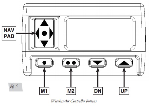
CONTROLLER DESCRIPTION
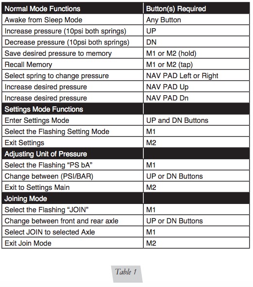
The controller has buttons M1 and M2 for controlling presets, UP and DN buttons that adjust the spring pressure, the NAV PAD that is used to select and control many different options, and the LCD to display pressures and other information to the user.
The controller has a LCD to provide the user feedback of system operation. This LCD will display air spring pressures, provide status of the system, and display fault detection messages.
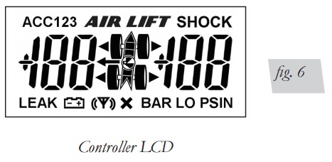
ICON DEFINITION

Battery is displayed when the battery voltage in the controller is low, a low battery voltage may prohibit a high strength wireless transmission and may result in a failed transmission.

Transmission Indicator is displayed when the controller is actively communicating with the Manifold.

Fail Indicator is displayed when we have any failure of the system for example, communication failure, valve blockage, or a leak.

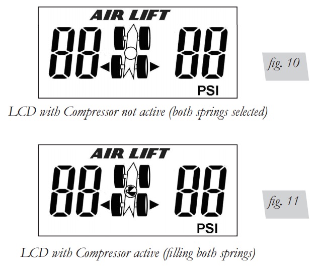
Compressor Indicator is displayed when the compressor is running and the system is filling a spring to the desired pressure.

Unit of measure will be indicated per the user setup.

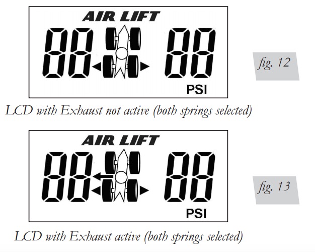
Exhaust arrow will be displayed when the manifold exhaust valve is active and the system is exhausting a spring to the desired pressure.

Accessory Icon will be active in the Settings mode
System Operation
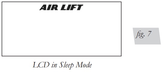
SLEEP MODE
The controller features a sleep mode to preserve the battery life. In this mode the Manifold is still active and will maintain the desired spring pressures
• In Normal Mode If no button has been pressed for 30 seconds the controller will enter Sleep mode
• LDC will only Displays the AIRLIFT Logo
• Backlight and Radio are turned off
• Any button press will recover to Normal Mode
If the controller does not go into Sleep Mode after 30 seconds, change the pressure by one or two psi. The controller will then go into Sleep Mode after 30 seconds.
NORMAL MODE
•The normal operating mode is used to adjust pressure of the air springs. To enter normal mode from sleep Mode press any button. To enter the settings mode press the UP and DN buttons together.
•To exit the settings mode press M2.
Increasing and decreasing desired pressure:
• Initial press of any button will wake up display and not perform any function
• Upon wake up the LCD will display the last desired pressure
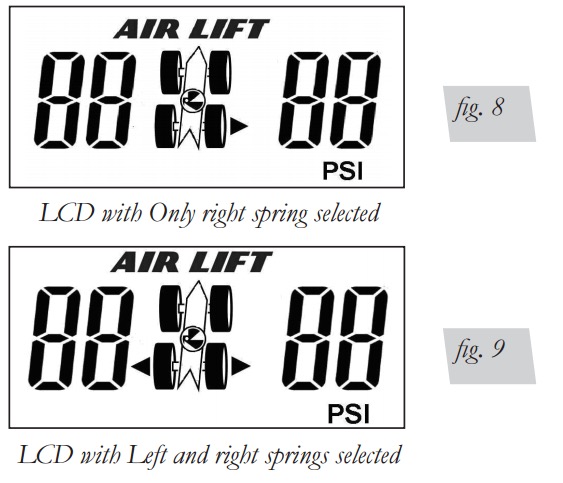
• If pressure adjustment is needed select the Air springs you would like to adjust
• Using the NAV PAD left and right buttons you can select / deselect the air springs to adjust
• The selection arrows will indicate which springs are selected
Increasing Pressure
• Pressing the NAV PAD up button will increase the desired pressure by 1 psig, or 0.1BAR depending on the unit of measure selected.
• Pressing the UP button will increment both left and right springs by 10psi or 1.0 BAR depending on the unit of measure selected
• The controller will send the new desired pressure 2 seconds after the pressure has not changed by the user.
• The compressor icon will be active to indicate when the compressor is running
Decreasing pressure
• Pressing the NAV PAD down button will decrease the desired pressure by 1 psig, or 0.1BAR depending on the unit of measure selected.
• Pressing the DN button will increment both left and right springs by 10psi or 1.0 BAR depending on the unit of measure selected.
• The controller will send the new desired pressure 2 seconds after the pressure has not changed by the user.
• The arrow in the middle of the display indicates when the manifold is exhausting the air springs.
Recalling the Presets
• Tap the M1 or M2 buttons to send the Memory 1 or Memory 2 settings as the new desired pressures.
• LCD Function
• The LCD will display the desired pressures for 2 seconds.
• The LCD will then display the actual spring pressures until the actual pressures equals the desired pressures.
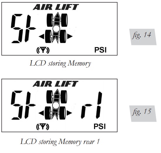
Saving Presets
• Press and hold the M1 or M2 buttons to save the current desired pressure to the Memory 1 or Memory 2.
• LCD Function
• LCD will display “St” on the left side of the screen to indicate it will be storing the desired pressure to Memory.
• LCD will display “r 1” or “r 2” on the right side of the screen to indicate the Memory location.
• Once the “Str” is displayed on the LCD release the button to save the pressure to Memory.
Error messages
• Leak Detection
• The controller will activate the LEAK icon on the controller when a leak has been detected
• Blockage Detection
• The controller will display “BL OC” to indicate there is a failure preventing an air spring from inflating or deflating
• Compressor Inoperable
• The controller will display “CO INP” if the compressor has run for too long and is in danger of overheating
SETTINGS MODE
In the settings mode the user can adjust the unit of measure, and join the manifolds with the controller. To enter and exit the settings mode, press the UP and DN buttons together.
• In the settings mode the display will display “ACC” on the top left corner to indicate settings mode
• The UP arrow will scroll through the different options in the settings Menu
• The options will flash in the settings menu, and be permanently on when the option is selected
• Join option
• When the word “Join” is flashing press the M1 button to enter the Join menu
• See Joining section for more information
• Press the M2 button to exit back to the Settings main menu

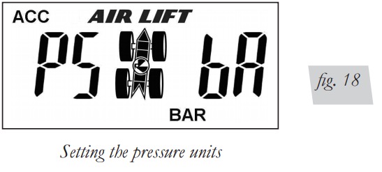
• Changing the unit of Pressure setting option.
• When the “PS BA” is flashing on the display press the M1 button to adjust the unit of measure.
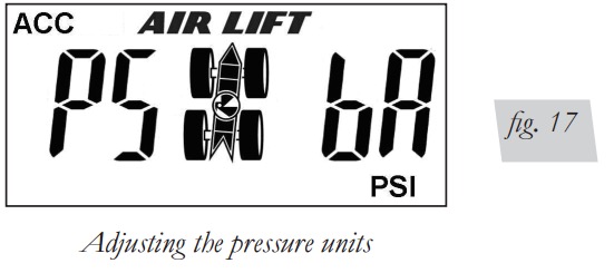
• The “PS BA” will now stop flashing
• Pressing the M1 button will now toggle between the unit of measure for the pressure
• The unit of measure will be displayed in the bottom right corner of the LCD
• Press the M2 button to exit back to the Settings main menu
JOINING THE CONTROLLER TO THE MANIFOLD
• Set the manifold into join mode
• Ground the join wire in the electrical harness
• Locate the YELLOW join wire with heat shrink on the end in the harness
• Remove the yellow wire from the cap leaving the cap atached to the harness
• Attach the exposed terminal to a good frame ground
• Cycle power to the manifold
• Manifold will boot in join mode and will click the exhaust solenoid 5 times fast, then 1 per second
• The manifold will stay in join mode for 30 seconds allowing time to set the controller into join mode
• Set the controller into join mode
• Press UP and DN buttons together to enter Settings Mode
• Press the M1 button when the display flashes “JOIn”
• Use the up and down buttons to select which manifold to join with
• JOIn r = Join with the manifold controlling the rear axle springs
• JOIn F = Join with the manifold controlling the front axle springs
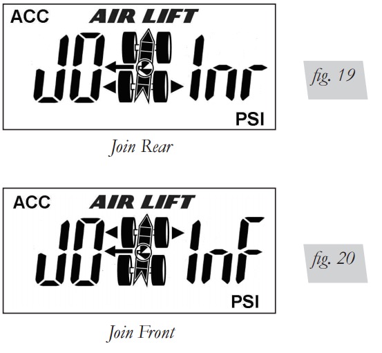
• Press the M1 button to join the controller to the selected manifold
• The display will show DONE when the joining process is complete
• The M2 button will exit back to the settings mode
• Press M2 button again to exit out of Settings Mode
• Disconnect yellow wire from ground
• Reinsert the yellow wire terminal into the molded cap
QUICK FUNCTION REFERENCE

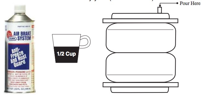
IMPORTANT: To Avoid Cold Weather Freeze-up
Add 4 oz. (1/2 cup) of “GUNK” Brand AIR BRAKE ANTI FREEZE
Directly into each flex member. Remove the air line and/or fitting from the air bag and fill directly. Gunk Brand Air Brake Anti-Freeze may be purchased at an automotive parts store or truck supply store.
WARNING: IF THE USER INSTALLS THE MANIFOLD OR COMPRESSOR IN THE CAB OF THE VEHICLE IN EXTREME WEATHER CLIMATES, DO NOT USE ANY ANTI-FREEZE PRODUCT IN THE SYSTEM AS EXHAUST FUMES CAN BE TOXIC.
CARE MUST BE TAKEN WHEN USING THIS PRODUCT! IT IS RECOMMENDED THAT THIS PRODUCT’S MSDS SHEET BE REVIEWED BEFORE USE! THIS CAN BE OBTAINED WHERE YOU PURCHASE THIS PRODUCT.
WARNING: DO NOT FILL THROUGH COMPRESSOR OR MANIFOLD — DAMAGE WILL OCCUR.
CAUTION: DO NOT USE ENGINE ANTI-FREEZE
Check fluid levels in flex member every year (add if needed).
Warranty and Returns Policy
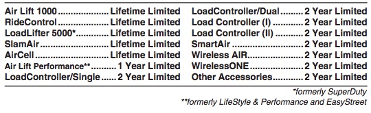
Air Lift Company warrants its products, for the time periods listed below, to the original retail purchaser against manufacturing defects when used on catalog-listed applications on cars, vans, light trucks and motorhomes under normal operating conditions for as long as Air Lift manufactures the product. The warranty does not apply to products that have been improperly applied, improperly installed, used in racing or off-road applications, used for commercial purposes, or which have not been maintained in accordance with installation instructions furnished with all products. The consumer will be responsible for removing (labor charges) the defective product from the vehicle and returning it, transportation costs prepaid, to the dealer from which it was purchased or to Air Lift Company for verification.
Air Lift will repair or replace, at its option, defective products or components. A minimum $10.00 shipping and handling charge will apply to all warranty claims. Before returning any defective product, you must call Air Lift at (800) 248-0892 in the U.S. and Canada (elsewhere, (517) 322-2144) for a Returned Materials Authorization (RMA) number. Returns to Air Lift can be sent to: Air Lift Company • 2727 Snow Road • Lansing, MI • 48917.
Product failures resulting from abnormal use or misuse are excluded from this warranty. The loss of use of the product, loss of time, inconvenience, commercial loss or consequential damages is not covered. The consumer is responsible for installation/reinstallation (labor charges) of the product. Air Lift Company reserves the right to change the design of any product without assuming any obligation to modify any product previously manufactured.
This warranty gives you specific legal rights and you may also have other rights that vary from state-to-state. Some states do not allow limitations on how long an implied warranty lasts or allow the exclusion or limitation of incidental or consequential damages. The above limitation or exclusion may not apply to you. There are no warranties, expressed or implied including any implied warranties of merchantability and fitness, which extend beyond this warranty period. There are no warranties that extend beyond the description on the face hereof. Seller disclaims the implied warranty of merchantability. (Dated proof of purchase required.)
Replacement Information
If you need replacement parts, contact the local dealer or call Air Lift customer service at (800) 248-0892. Most parts are immediately available and can be shipped the same day.
Contact Air Lift Company customer service at (800) 248-0892 first if:
• Parts are missing from the kit.
• Need technical assistance on installation or operation.
• Broken or defective parts in the kit.
• Wrong parts in the kit.
• Have a warranty claim or question.
Contact the retailer where the kit was purchased:
• If it is necessary to return or exchange the kit for any reason.
• If there is a problem with shipping if shipped from the retailer.
• If there is a problem with the price.
Contact Information
If you have any questions, comments or need technical assistance contact our customer service department by calling (800) 248-0892, Monday through Friday. For calls from outside the USA or Canada, our local number is (517) 322-2144.
For inquiries by mail, our address is PO Box 80167, Lansing, MI 48908-0167. Our shipping address for returns is 2727 Snow Road, Lansing, MI 48917.
You may also contact us anytime by e-mail at [email protected] or on the web at www.airliftcompany.com.
Templates

Need Help?
Contact our customer service department by calling (800) 248-0892, Monday through Friday. For calls from outside the USA or Canada, our local number is (517) 322-2144.
Register your warranty online at www.airliftcompany.com/warranty
