 FREE 1 to 3-Day Delivery on Orders $149+ Details

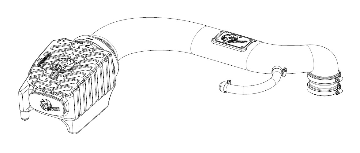
How to Install AFE Momentum GT Pro DRY S Cold Air Intake (97-06 4.0L Wrangler TJ) on your Jeep Wrangler
Tools Required
- 8mm, 10mm, and 13mm sockets
- 1/4" and 8mm nut drivers or flat blade screwdriver
- 10mm wrench
- pliers

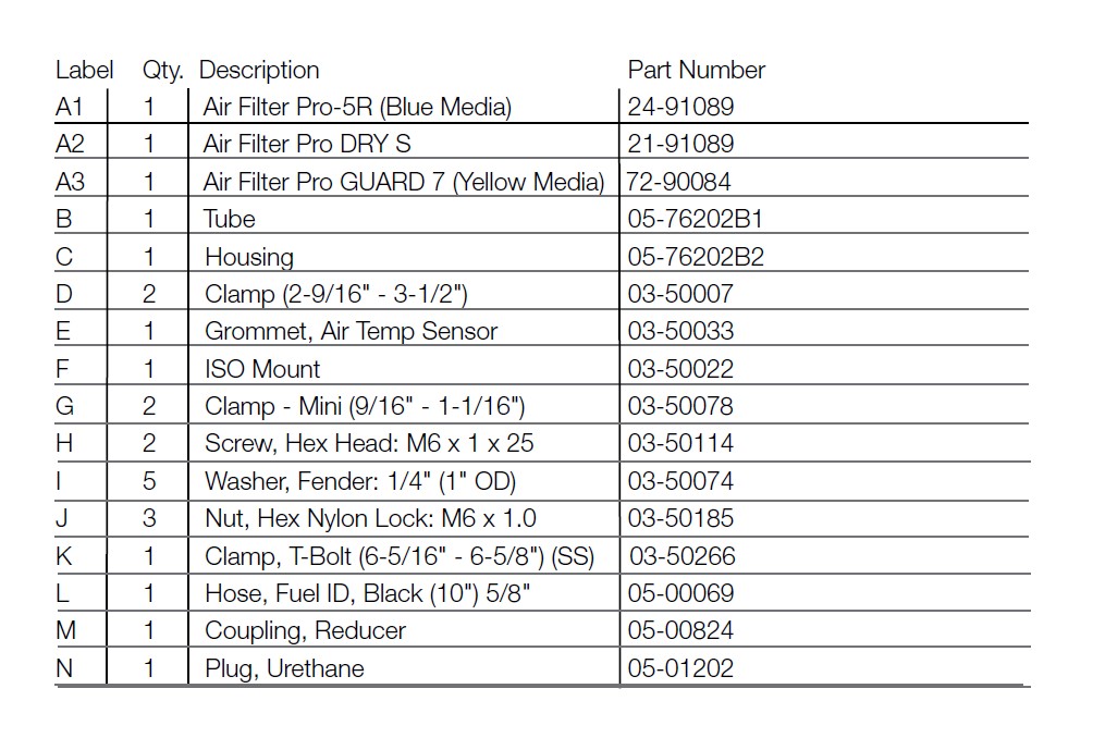
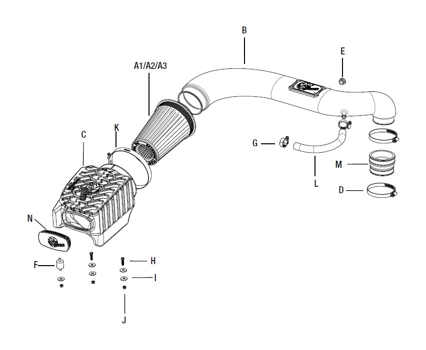
Shop Parts in this Guide
• Please read the entire instruction manual before proceeding.
• Ensure all components listed are present.
• If you are missing any of the components, call customer support at 951-493-7100.
• Ensure you have all necessary tools before proceeding.
• Do not attempt to work on your vehicle when the engine is hot.
• Disconnect the negative battery terminal before proceeding.
• Retain factory parts for future use.
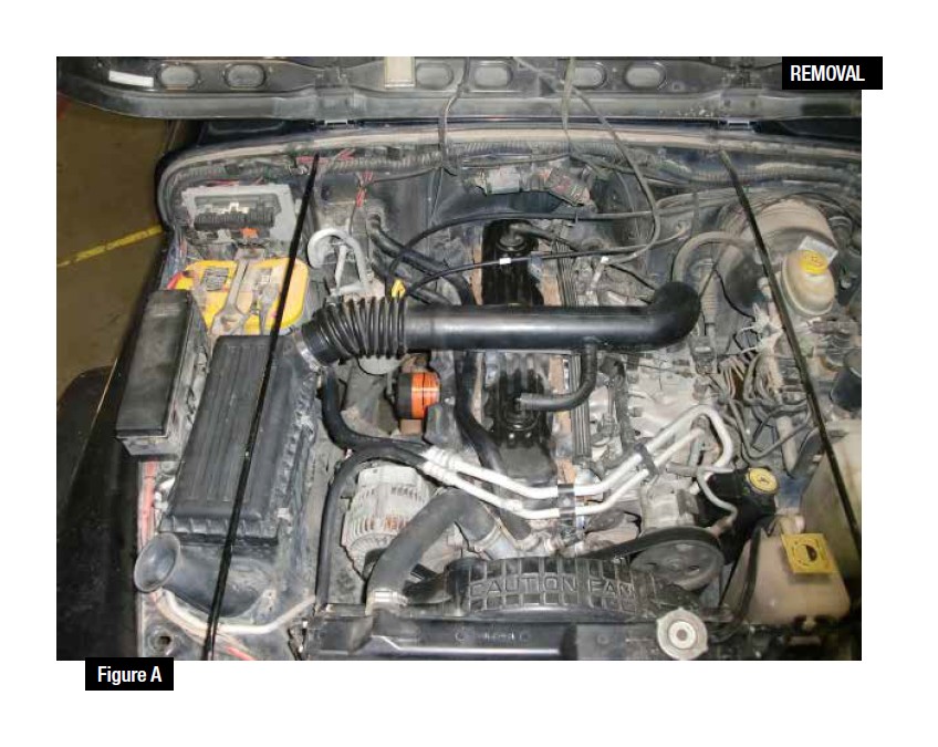
Refer to Figure A for Step 1-3
Step 1:Loosen the clamps on the intake tube using an 8mm nut driver.
(2004-2006 Models only): Disconnect the temperature sensor harness located on the back side of the intake tube.
Step 2: Completely remove the Crank Case Vent (CCV) hose from the vehicle.
Step 3: Remove the intake tube.
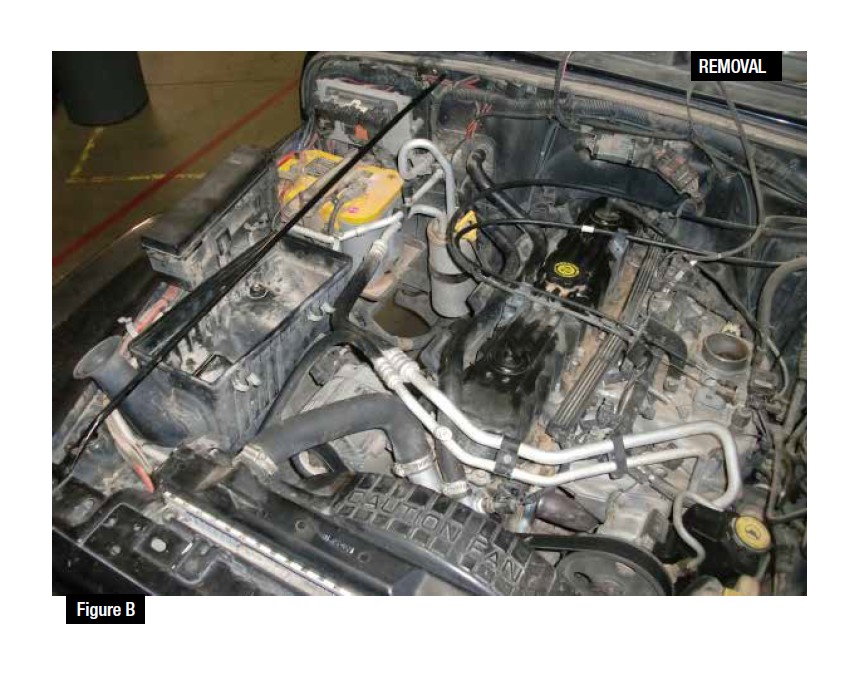
Refer to Figure B for Steps 4-5
Step 4: Unclip the top of the air box and remove it from the vehicle.
Step 5: Remove the OE air filter from the lower half of the air box.
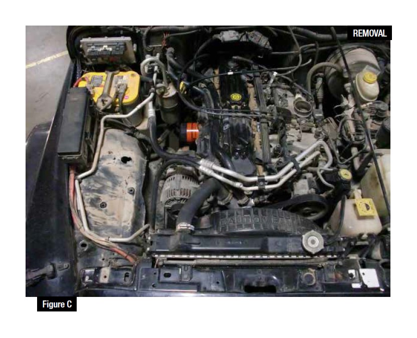
Refer to Figure C for Steps 6-8
Step 6: Remove the small round cross bar that goes from the front radiator support to the fire wall on the passenger side.
Step 7: Using an 8mm socket, loosen all three of the screws on the bottom of the air box.
Step 8: Pull the lower half of the factory air box out of the vehicle.
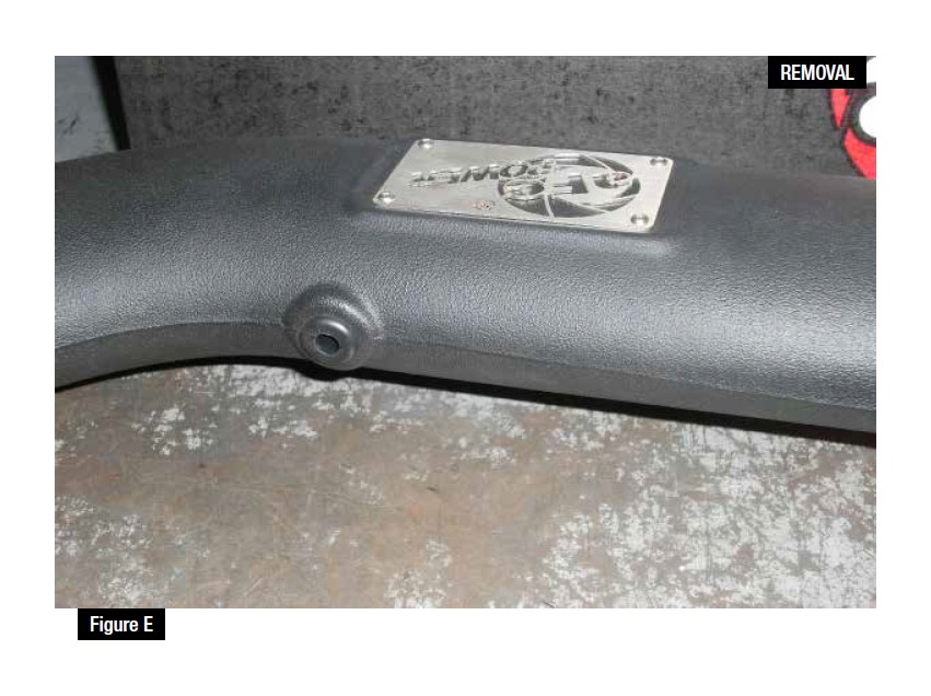
Refer to Figure E for Steps 9-10
Step 9: Remove the bolts from the factory air box.
Step 10: Press out the metal sleeves from (2) two of the grommets and then remove the (2) two grommets completely.
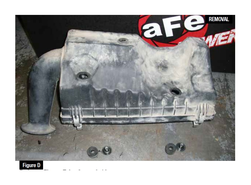
Refer to Figure D for Steps 11-13
FOR 2004-2006 MODELS EQUIPT WITH TEMP SENSOR ONLY! IF TEMP SENSOR IS NOT EQUIPT THEN SKIP TO FIGURE F!
11: Remove the temp sensor from the back of your factory intake tube by rotating it counterclockwise and pulling it out. Be careful not to break the small tab that locks the sensor in place.
12: Drill out an 11/16" diameter hole in the back of the new aFe intake tube in the location shown in the picture. Deburr all sharp edges.
13: Insert the supplied grommet into the hole, and then press your temp sensor into the grommet.
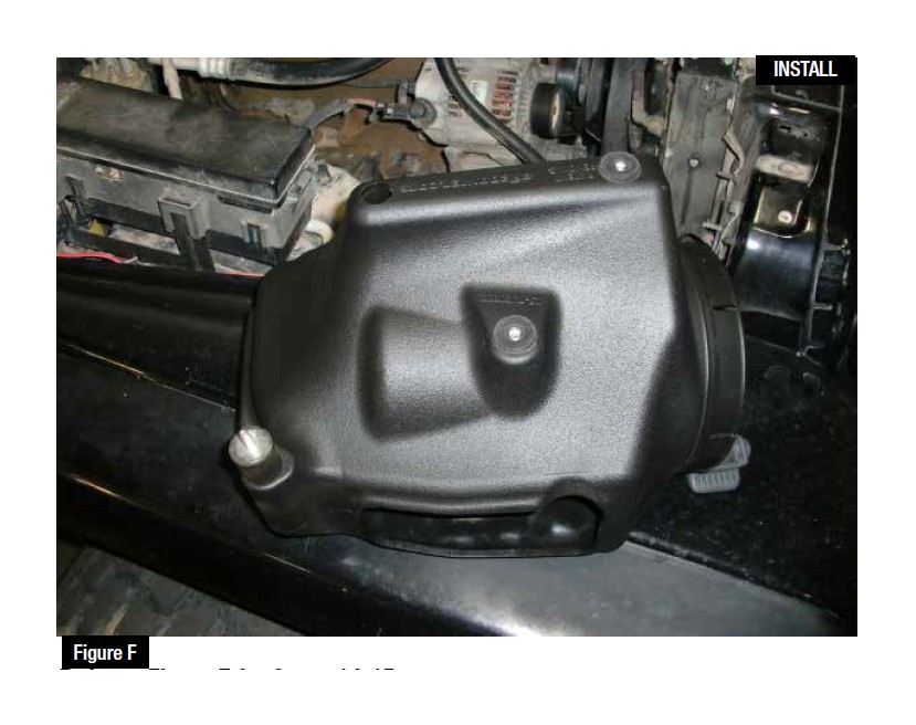
Refer to Figure F for Steps 14-15
Step 14: Install the grommets into the two locations shown in the picture and insert the metal sleeves from inside of the housing so that the flat part is on the inside.
Step 15: Insert the rubber isolation mount into the threaded insert on the bottom of the housing and tighten by hand.
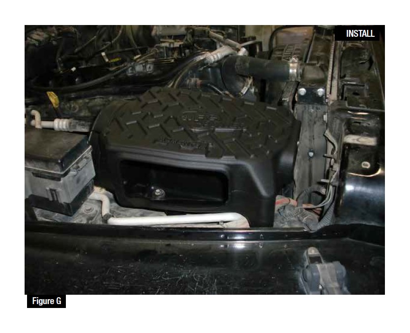
Refer to Figure G for Steps 16-17
Step 16: Install the new housing into the vehicle and make sure that the rubber isolation mount lines up with the slotted hole on the fender well. Insert the two M6x1x25mm furnished bolts with two flat washers through the grommmets on the inside of the housing.
Step 17: Place a flat washer and then a nut on all three bolts that pass through the fender well. Tighten the housing in place, but do not over-tighten the isolation mount.
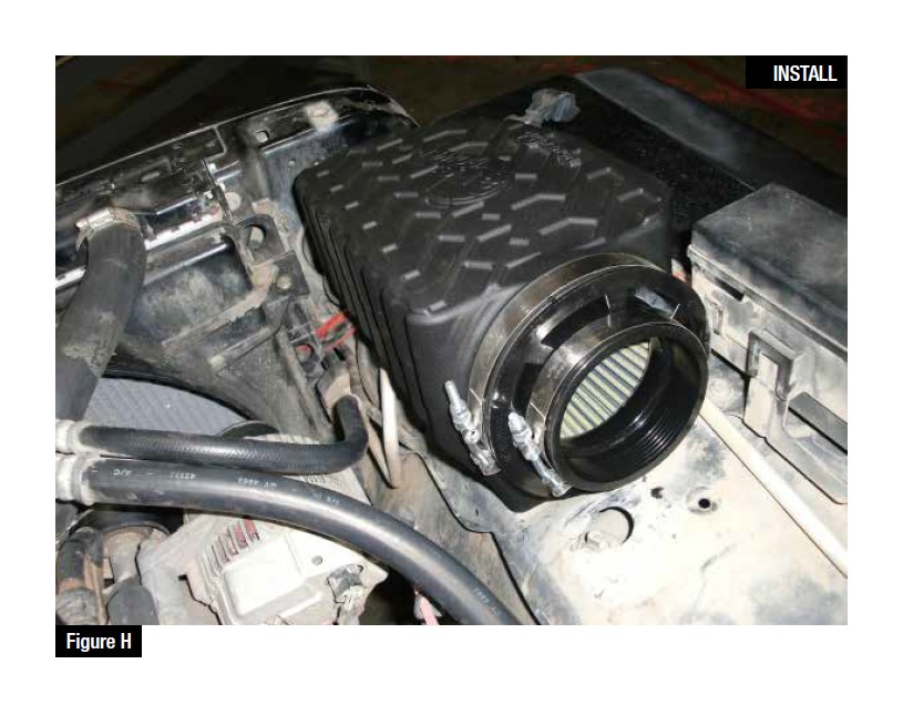
Refer to Figure H for Steps 18-19
Step 18: Install the large clamp over the back side of the flange on the housing.
Step 19: Install the filter with clamp into the back of the housing. (Note: if this interface slips apart, then acetone can be applied to both the filter and housing in this area to remove and mold release oil that is causing it to slip.)
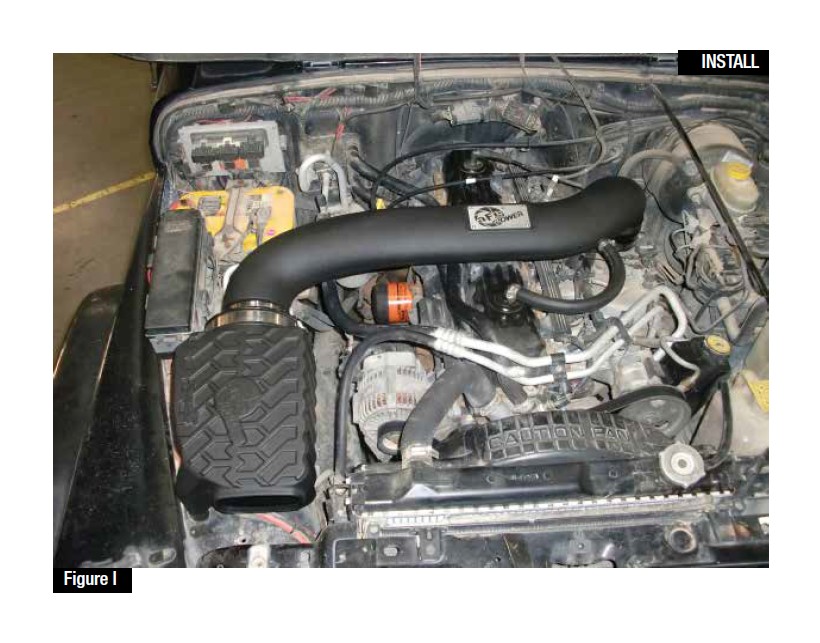
Refer to Figure I for Steps 17-20
Step 17: Slide the two smaller clamps onto the coupling and then install the coupling, with the small diameter side facing down, onto the throttle body. Do not tighten any of the clamps yet.
Step 18: Install the intake tube into the back of the filter and then rotate it down into the coupling located on the throttle body side. Position all of the parts so that they are lined up and then tighten all 4 clamps.
FOR 2004-2006 MODELS EQUIPT WITH TEMP SENSOR ONLY:
Step 19: Plug in the temp sensor wire.
Step 20: Slide the two smallest clamps over each end of the supplied vent hose. Connect the new vent hose to the CCV port and to the port on the intake tube and tighten both clamps.
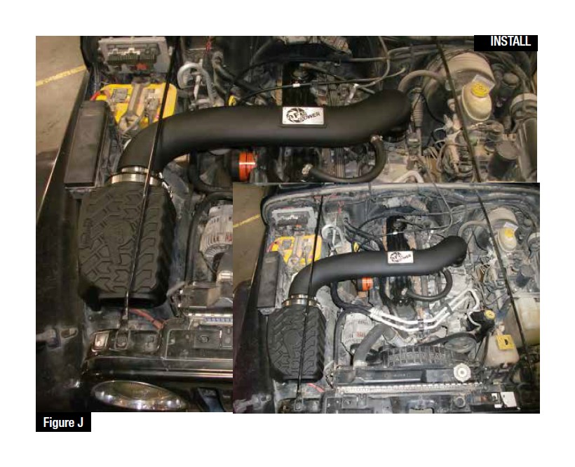
Refer to Figure J for Steps 21-22
Step 21: Reinstall the cross bar that goes from the firewall to the radiator support. Tighten both bolts.
Step 22: If desired, the urethane plug can be installed to reduce some of the intake noise. Your installation is now complete.
NOTE: Retighten all connections after approximately 100-200 miles.
Place enclosed CARB EO sticker on or near the device on a smooth, clean surface.
EO identification label is required to pass the smog inspection.

