 FREE 1 to 3-Day Delivery on Orders $149+ Details

How to Install Poison Spyder BFH II Rear Bumper w/ Recessed LED Light Mounts - Bare Steel
Installation Time
2 hours
Tools Required
- Reciprocating saw with bi-metal blade OR pneumatic cutoff wheel OR plasma cutter OR similar tool for cutting metal
- Mechanic’s tool set with an assortment of wrenches, sockets
- Angle grinder
- Drill motor with 1/4” and 1/2” drill bits
- Fine-tip felt marker
- Primer and paint

Shop Parts in this Guide
APPLICATIONS
These installation instructions apply to the following Poison Spyder products:
17-17-021-D JK BFH™ II Rear Bumper - Tabs
17-17-021-DL JK BFH™ II Rear Bumper - Tabs - Lights
17-17-040-D JK BFH™ II Rear Bumper - Hitch - Tabs
17-17-040-DL JK BFH™ II Rear Bumper - Hitch - Tabs - Lights (Shown)
PARTS LIST
Please check your packages immediately upon arrival to ensure that everything listed is included, and to check for damage during shipping. If anything is missing or damaged, call Poison Spyder at (951) 849- 5911 as soon as possible.
(1) JK BFH™ II Rear Bumper
(1) JK BFH™ II Rear Frame Cut Template
(1) JK BFH™ II Rear Bumper Hardware Kit
PN: HWKIT-17-17-020 includes:
(4) 3/8-16 X 1 Gr8 hex head cap screw
(4) 3/8 SAE Hardened Flat Washer
(2) 3/8-16 Extruded U-Nut Clip
(2) 3/8-16 Serrated Flange Nut
BEFORE YOU BEGIN
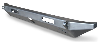
The Poison Spyder Customs BFH II Rear bumper comes as unpainted, bare steel. You will want to either powder coat or paint the bumper prior to final installation, however it is recommended that a complete installation be performed first, with the bare/ unpainted bumper to ensure fitment without damaging the paint or powder coat finish. Poison Spyder Customs is NOT RESPONSIBLE for paint or powder coating costs, damage to paint or powder coating, or costs associated with inadvertently painting or powder coating components that are defective or were shipped or assembled in error. It is the customer’s responsibility to pre-install and verify that all parts are correct prior to paint or powder coat.
IMPORTANT: It is highly recommended to install the Poison Spyder JK BFH II Rear Crossmember in conjunction with this bumper. However, at the installer’s discretion, the JK BFH II Rear Bumper may be installed by itself, without the replacement crossmember. Note that this will leave the Jeep without the full strength of an intact rear crossmember, and the installer does so at his/her own risk. Poison Spyder makes no warranty for the integrity of the Jeep’s frame on JK BFH II Rear Bumper installations where the JK BFH II Rear Crossmember was not properly installed.
INSTALLATION PROCEDURE
NOTE: The first 10 steps of the instructions provided here are for those who intend to install this bumper WITHOUT the Poison Spyder JK BFH II Rear Crossmember. If you ARE installing the JK BFH II Rear Crossmember, install it first, following the instructions that came with the crossmember, then skip past the steps that are duplicated here (marking and cutting the crossmember).
1. Park the Jeep on a flat, level surface and set the parking brake. You will want to wear eye protection beyond this point in time.
2. Remove existing rear bumper. Keep the OE hardware that attached the bumper to the frame rails, as some of it will be re-used.
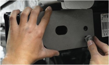
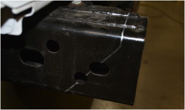
3. Attach the provided JK BFH II Rear Frame Cut Template (laser cut from steel plate) to the side of the frame rail, using two of the OE bumper bolts as shown in the following photo. Make sure that the template is exactly aligned with the frame rail as the bolts are tightened. In other words, the top and bottom edges of the template must be parallel with the top and bottom of the frame rail.
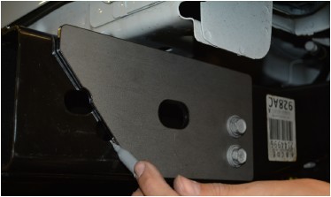
4. Use a light-colored felt-tip marker or scribe to mark a cut-line along the diagonal edge at the rearward end of the cut template.
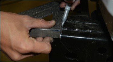
5. Continue marking the cut-line over the top surface of the frame rail. Use a square to ensure that the cut-line is exactly perpendicular to the outer edge of the frame rail. Use the same technique to continue the cut line on the bottom of the frame rail.
6. Repeat the cut-line marking process for the other frame rail.
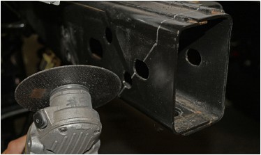
7. Use a torch, plasma cutter, pneumatic or electric cutoff wheel, reciprocating saw, or the cutting device of your choice to cut the outboard, top and bottom surfaces of each frame rail along the cut-lines made in the previous steps.
8. If not installing the Poison Spyder JK BFH II Rear Crossmember, we recommend leaving as much of the rear crossmember intact as possible. However, a significant portion of its rear-lower corner will have to be cut away to provide clarance for the JK BFH II Rear Bumper. Use your best judgement to cut away a section of the crossmember along the same plane as that defined by the cut-lines on the frame rails. It would be best to be conservative in your initial cuts, cutting away as little as possible, then test-fit the bumper, then cut a little more, until the bumper fits without interference with the remaining crossmember. OPTIONAL: at the installer’s discretin, a piece of flat plate steel may be cut to fit over the cut crossmember and welded in place to reinfoce the integrity of the crossmember.
Note that the following photos depict an installation along with the JK BFH II Rear Crossmember, however the procedures henceforth are the same regardless of whether the replacement crossmember has been used.
9. With the help of a friend, lift the BFH II Rear bumper into place, over the cut ends of the frame rails.
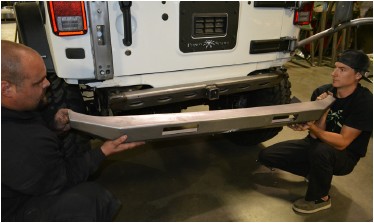
10. Re-install two of the OE bumper bolts on each side, through the holes provided on the bumper’s mounting plates into the existing threaded holes in the side of the Jeep’s frame rail. Do not fully tighten them yet.
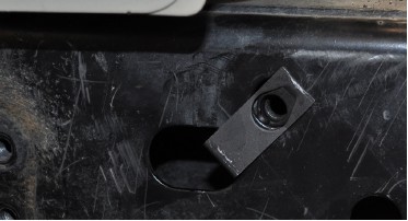
11. Insert a 3/8-16 X 1 Gr8 Hex Head Cap Screw (with 3/8 Gr8 Flat Washer) through the hole on the bottom of the BFH II Rear Bumper where it fits over the frame rail.
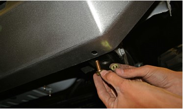
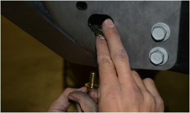
Insert a 3/8-16 Gr8 Serrated Flange Nut through the large oval hole on the side of the bumper’s mount plate, and thread it on to the bolt that was inserted from below. It will be possible to hold the nut in place with a finger, but not possible to reach it with a wrench. The serrations on the bottom of the flange will work to keep the nut from spinning as the bolt is tightened with a wrench on the outside/bottom of the bumper. Install and tighten this hardware on both sides of the bumper.
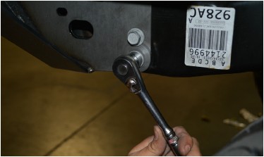
12. Tighten the 4 OE bumper bolts (2 per side) that were loosely installed in a previous step.
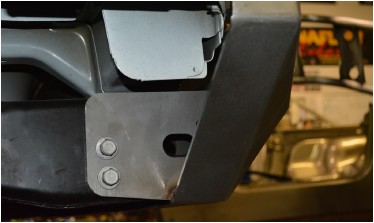
13. Note the third bolt hole in the mounting flange, just above and rearward of the oval-shaped hole on either side of the bumper. On some JK’s there may already be a hole in the frame rail at that location, on one or both sides. If not, use a felt-tip pen or auto-punch to mark the location of the third bolt hole on the frame rail, for each side. Make sure your mark is centered in the hole in the mounting flange.
14. Remove the bumper.
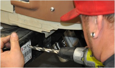
15. Drill through the crossmember on each side (if necessary), at the third bolt hole locations marked in a previous step. Start with a smaller drill size such as 1/4”, as a pilot hole. Then step up to the 1/2” bit for the final hole size. Use a file, grinder or sandpaper to de-burr the edges of the holes.
16. Primer and paint any bare metal from cutting and grinding the frame rails and crossmember, as well as the bare metal along the inside surface of any holes that were drilled.
17. Install the supplied 3/8-16 Clip-Nuts into each frame rail. Slip the clip-nut through the existing ovalshaped hole, and lodge the extruded barrel of the clip nut into the nearby 1/2” hole that was drilled in the previous step. Make sure the extruded side of the cli-nut is oriented toward the inside of the frame rail and the flush side of the cli-nut is along the exterior surface of the frame rail.
18. Paint or powder-coat the bumper in the color of your choice. If painting yourself, careful preparation will make a big difference in the quality and longevity of your paint job, even using “rattle can” aerosol paints. Begin by thoroughly cleaning the bumper with solvent or de-greaser, then make sure all residue is removed. Even if you use cheap paint, try to use a good quality primer. “Etching” primers are best to use on bare, unpainted metal. Allow it to properly dry before painting, and between paint coats.
19. If your JK BFH II Rear Bumper came with the optional integrated light bar mounts, mount them inside the bumper using the tabs provided, making sure that wiring is accessible to complete the connections after the bumper has been installed.
20. Re-install the bumper using the hardware that was used in the pre-installation process. Finish by adding a 3/8-16 X 1 Gr8 Hex Head Cap Screw, with 3/8” Hardened Flat Washer, through the hole in the mounting flange on each side of the bumper, into the clip-nut that was installed in a previous step.
21. If LED light bars were installed in the light pockets, finish wiring them according to the light bar manufacturer’s specifications.
Congratulations, you have installed your Poison Spyder Customs JK BFH II Rear Crossmember! You may now either use your Jeep with only the Crossmember as a “minimalist” bumper, or you may proceed with installation of the Poison Spyder JK BFH II Rear Bumper!
