 FREE 1 to 3-Day Delivery on Orders $119+ Details

How to Install Poison Spyder LED Resistor Kit for LED Tail Lights on your Wrangler
Tools Required
- Electrical multi-meter or test light
- Electrical wire cutter/crimper
- Channel-lock pliers
Shop Parts in this Guide
LED lamps draw much less current than standard incandescent lamps. On some late model vehicles, this variation can cause the turn signals to flash at an abnormal rate and/or cause error codes in the electronics system. This kit is designed to simulate the load of incandescent lamps in order to correct these problems. Installation is fairly simple with the right tools and good mechanical/electrical abilities. If you are not confident in your skills, please seek the help of a professional to perform the installation. Please read through these entire instructions before proceeding with installation.
PARTS LIST
Please check your packages immediately upon arrival to ensure that everything listed is included, and to check for damage during shipping. If anything is missing or damaged, call Poison Spyder at (951) 849-5911 as soon as possible.
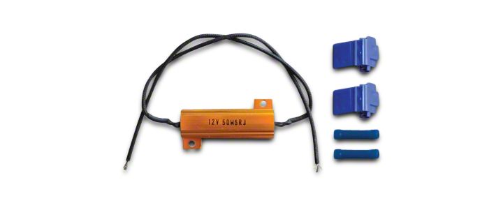
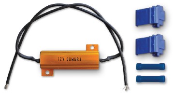
(1) Load Resistor with lead wires
(2) 18-14 Ga. Wire Tap Connectors
(2) 18-14 Ga. Butt Connectors
BEFORE YOU BEGIN
These Load Resistors are primarily used in conjunction with LED taillights on JK Jeeps, which are a commonly used with Poison Spyder Crusher Corners. It is assumed that installation of the LED’s is already completed, either as part of a Crusher Corner installation or by some other method. These instructions only cover the installation of the Load Resistors themselves.
TWO Load Resistor Kits are required for one Jeep, as one will be installed at each taillight. The following procedure assumes installing the Load Resistor in conjunction with the specific LED Taillight and Pigtail sold by Poison Spyder Customs.
The Load Resistor is installed behind the LED taillight assembly, inside the body panel of the Jeep. If the LED Taillight is already installed, remove it to gain access to the space behind it and the OE wiring.
INSTALLATION PROCEDURE
1. Park vehicle on a level surface, place the transmission in gear or park and set the emergency brake.
2. Reach through the LED taillight hole and locate the taillight wiring section of the OE wiring harness. It will either be cut or have the OE plug from where it attached to the OE taillight assembly. Carefully pull as much of the harness out through the hole as possible without damaging it, making it easier to work on the wiring.
3. Identify which wires in the harness are the hot leads for the running lights and for the stop/turn lights. Use a test light or multi-meter to ID these wires. Turn the running lights on and probe each wire until you find the “hot” one. Then turn on the turn signal for whichever side you’re working on to determine which wire is correct for that circuit.
4. Study the diagram at the top of page 2 of these instructions. Note that there are three wires in the pigtail coming from the LED taillight: black, red and white.
4. Use one of the Wire Tap Connectors to tap one of the Load Resistor leads into the RED wire from the LED Pigtail. These Wire Tap Connectors work by piercing through the wire insulation. To install them, slide the through- wire (in this case, the red wire from the LED Pigtail) through the slot in the connector that goes all the way through. Leave a few inches of the red wire poking through the other side of the connector. Then insert the lead from the Load Resistor (it doesn’t matter which one) into the non-through slot in the connector, and push it in until it hits the internal stop. Next, use the channel-lock pliers to crimp the metal tang down into the connector, which pierces the insulation and completes the tap. Finish by clasping the connector’s cover shut.
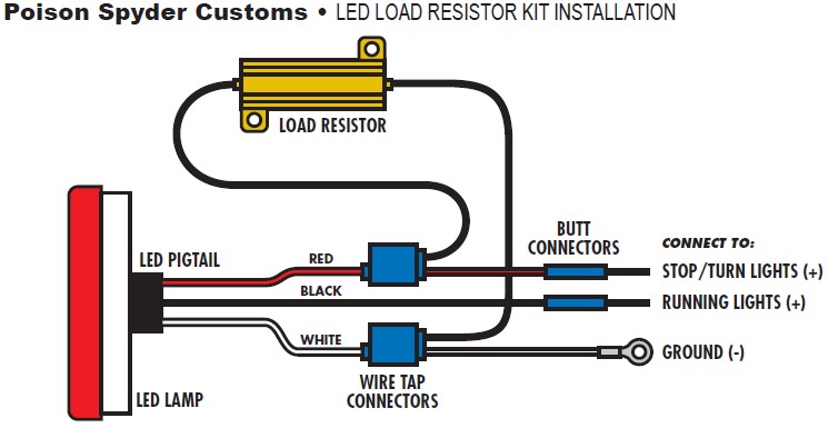
5. Use a Butt Connector to connect the end of the red wire to the Stop/Turn Lights hot lead in the OE harness, which you identified in Step 3.
6. Use the other Wire Tap Connector to tap the remaining Load Resistor lead into the WHITE wire in the LED Pigtail. Repeat the procedure from Step 4 for installing the Wire Tap Connector.
7. Attach the ring terminal at the end of the white wire to a suitable ground.
8. Use the remaining Butt Connector to connect the end of the BLACK wire in the LED Pigtail to the Running Lights hot lead in the OE wiring, which you identified in Step 3.
9. With these connections completed, plug the LED Lamp into the LED Pigtail and test operation of the running lights, stop, and turn lights. If they do not work correctly, check all of your connections and the routing of your wiring, using the diagram above for reference.
10. Affix the Load Resistor to some stationary location inside the body panel. Note that it can develop heat, just like the incandescent lamp it is simulating, so be careful not to mount it to or near anything that can melt or be damaged by heat, such as other wiring, plastic items, painted surfaces, etc.
11. Re-install the LED Lamp into place.
