FREE 1 to 3-Day Delivery on Orders $119+ Details

How to Install Synergy Lower Control Arm & Track Bar Hardware Kit (07-18 Wrangler JK) on your Jeep Wrangler
Shop Parts in this Guide
GENERAL NOTES:
These instructions are also available on our website; www.synergymfg.com. Check the website before you begin for any updated instructions and additional photos for your reference.
The following instructions cover the complete installation of 8050 hardware kits , including lower control arm, upper control arm and track bar hardware.
The installation of this hardware can be done on the ground with the weight of the vehicle sitting on its suspension.
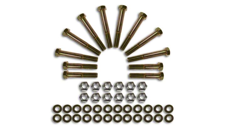
INCLUDED COMPONENTS:
8050
(8) 9/16-18 UNF x 4.0" long F911 bolts (LCAs)
(4) 9/16-18 UNF x 3.0" long F911 bolts (TBs)
(12) 9/16-18 UNF G9 Stover top lock nuts
(24) 9/16" Extra Thick G9 hardened flat washers
(1) M14-2.0 x 80mm Grade 10.9 bolt (2012 Front Frame Side Track Bar Bracket)
(1) M14-2.0 GR9 Stover top lock nut
8050-01
(4) 9/16-18 UNF x 3.50" long F911 bolts (RUCAs)
(4) M12 X 1.50 85MM (3.50") long GR10.9 bolts (FUCAs)
(4) M12 x 1.50 G9 Stover top lock nuts
(4) 9/16" Extra Thick G9 hardened flat washers
(8) 1/2" Extra Thick G9 hardened flat washers
(2) Rear Upper Control Arm Nut Tab, Frame Side
(2) Rear Upper Control Arm Nut Tab, Axle Side
INSTALLATION
1. We recommend installing the hardware one suspension link at a time. This will enable the hardware to easily be replaced with the vehicle sitting under its own weight.
Take note, the rear upper control arm hardware is easier to get to with the rear wheels removed. This will be covered later in the instructions.
2. Begin with the front end. Start with the lower control arms. Replacing one bolt at a time. Take note of orientation of all hardware, reinstall with the new hardware going the same direction as the OEM.
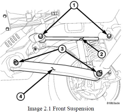
3. Remove bolts labeled 3 in image 2.1 above. Replace with 9/16-18 UNF x 4.0" long F911 bolts. The head of the bolt should be toward the outside of the vehicle and the nut should be towards the inside. Use a 9/16” washer under both the head of the bolt and under the nut. Torque to 130 ft-lbs.
4. Next, replace the front upper control arm hardware. Again, match the bolt orientation to the OEM hardware.
5. Remove the bolts labeled 1 in image 2.1 above. Replace with M12 X 1.50 85MM (3.50") long GR10.9 bolts. Use a ½” washer under both the head of the bolt and under the nut. Torque to 80 ft-lbs.
6. Last on the front end is the front track bar hardware. Begin at the frame side and remove the bolt labeled 2 in image 6.1 below.
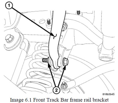
7. Replace with a 9/16-18 UNF x 3.0" long F911 bolt.
NOTE - 2012 models feature a spherical bearing on the OEM track bar which requires a metric bolt at the frame side. If installing on a 2012 vehicle, use the M14-2.0 x 80mm Grade 10.9 bolt included in the kit.
8. Use a 9/16” washer under both the head of the bolt and under the nut. Torque to 130 ft-lbs.
9. Now move onto the axle side. Remove the bolt labeled 1 in image 9.1 below.
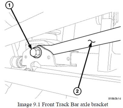
10. Replace with a 9/16-18 UNF x 3.0" long F911 bolt. Use a 9/16” washer under both the head of the bolt and under the nut. Torque to 130 ft-lbs.
NOTE - It helps to have someone turn the steering wheel to help align the track bar bushing to the bracket.
11. Move onto the rear suspension next.
12. Begin with the rear upper control arms. Note, it is easier to replace these with the rear tires removed. If removing the rear tires, be sure to use jack stands and safely support the vehicle prior to working under it.
13. Remove the hardware attaching the upper control arm to the vehicle.
Note, this hardware utilizes specialized nut tabs to ease installation, do not retain the OEM hardware as the 8050-01 kit comes with new grade 9 nut tabs.
14. Install 9/16-18 UNF x 3.50" long bolts in the rear upper control arm locations. Match orientation of the OEM hardware and use the appropriate nut tabs in the same fashion as stock. Use a washer under the bolt head. Do not use a washer under the nut tab. Torque hardware to 130 ft-lbs.
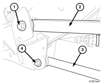
15. Next, remove the hardware attaching the rear lower control arms. Start at the frame side. Remove bolt 4 in the image above.
16. Replace using a 9/16-18 UNF x 4.0" long F911 bolt. Use a washer under both the head of the bolt and the nut. The bolt should be oriented with the bolt head outside of the frame and the nut on the inside. Torque to 130 ft-lbs.
17. Repeat step 16 for the lower control arm bolt at the axle side. Bolt 4 in image 17.1 below.
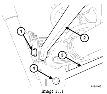
18. Note orientation of axle side lower control arm bolts. They must be oriented with the bolt head towards the inside of the vehicle, and the nut on the outside nearest the wheel.
19. Last step is the rear track bar hardware. Begin at the axle side and remove bolt 1 in image 17.1 above.
20. Replace with a 9/16-18 UNF x 3.0" long F911 bolt. Use a washer under both the bolt head and nut. Torque to 130 ft lbs.
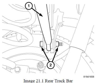
21. Repeat step 20 at the frame side track bar mount. Remove bolt 2 in image 21.1 below and replace with a 9/16-18 UNF x 3.0" long F911 bolt. Again, use a washer under both the bolt head and nut. Torque to 130 ft-lbs.
Note, it helps to have a friend push on the jeep from the side to help align the track bar bolt.