 FREE 1 to 3-Day Delivery on Orders $119+ Details

How to Install a Raxiom OE-Style Navigation w/ Bluetooth & Back-up Camera on your 2007-2017 Jeep Wrangler JK
Installation Time
1 hours
Tools Required
- 7mm Socket
- socket wrench
- socket extension
- interior removal tool
- wire cutter
- electical tape
Contents:
(1) - Raxiom Head Unit
(1) - Headphone Jack With Wire (A)
(1) - GPS Antennae With Wire (B)
(1) - Amplifier Pre-Outs Wire Harness (C)
(1) - External Microphone With Wire (D)
(1) - Satellite Radio Wire Harness (E)
(1) - Camera With Wire (F)
(1) - Camera / Aux 2 in Wire Harness (G)
(1) - Camera Intermediate Wire Harness (H)
(1) - Second Zone Wire Harness (I)
(1) - Main Wire Harness (J)
(2) - Mounting tabs
(8) - Mounting tab screws
(1) - Hole Saw
(1) - Adhesive Metal Plate
(1) - Cleaning Cloth
(2) - Small Head Unit Mounts
(2) - Large Head Unit Mounts
(1) - Antennae Adapter
It is recommended that you have an additional person available to help during this installation, parts can be awkward to hold and support by yourself. Block wheels and set parking brake before beginning work. Remove the BLACK (-) negative cable from the battery.
2007-2010 Wrangler Raxiom Navigation
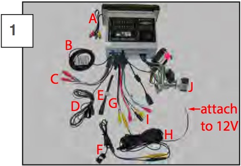
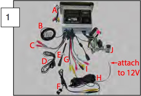
Above is a diagram of the wires included with the head unit. The GPS Antennae With Wire (B), External Microphone With Wire (D) and Camera With Wire (F) should be mounted in their respective areas, then the wires should be routed to the head unit and connected.
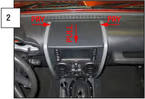
Pry up both sides of the rear center dash cover. Once the back is loose, pull it toward you and remove it from the vehicle.
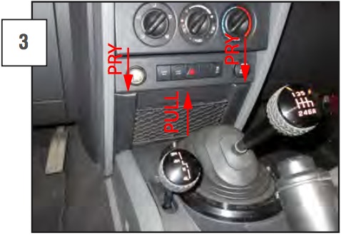
Pry out the top of the netting trim. Once the top is loose pull up on the trim and remove it from the vehicle.
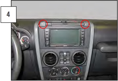
Remove the (2) 7mm screws, that are retaining the radio bezel.
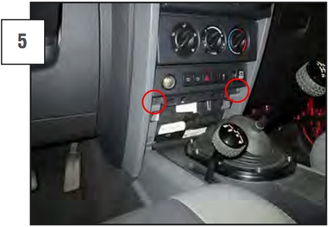
Remove the (2) 7mm screws holding the bottom of the radio bezel in place.
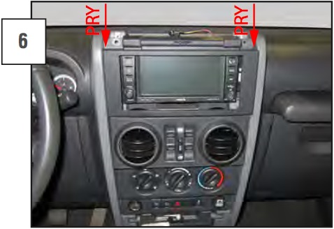
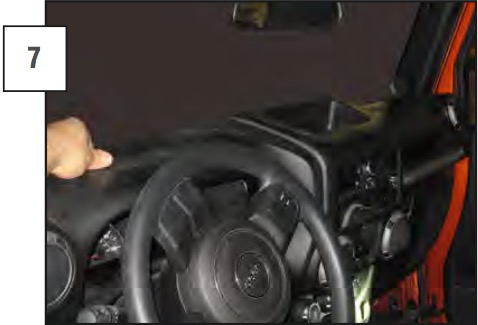
Pry out on the top of the radio bezel. Pull the bezel away from the dashboard.
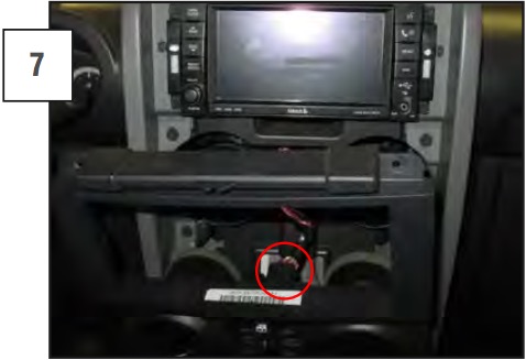
Unplug the power window wire harness if equipped.
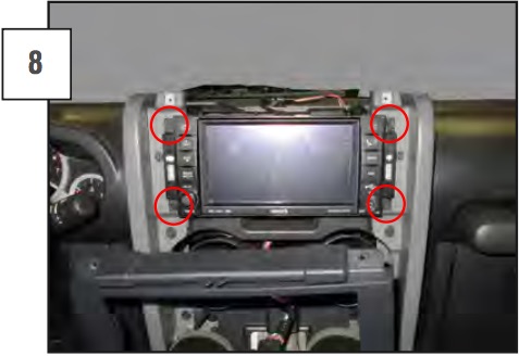
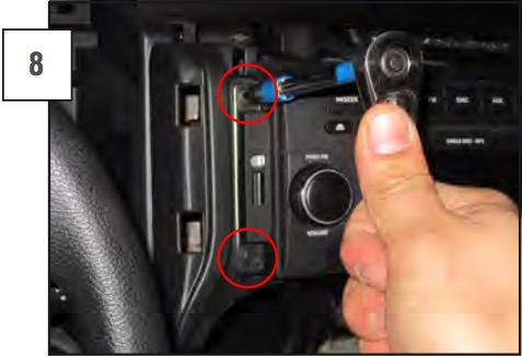
Remove the (4) radio head unit retaining screws from the stock head unit. There will be (2) on each side of the head unit.
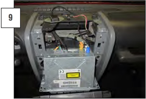
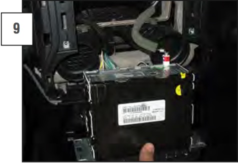
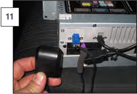
The head unit can be pulled out of the dash. Unplug all wiring from the back of the stock head unit and remove it from the vehicle.
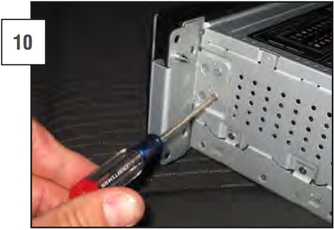
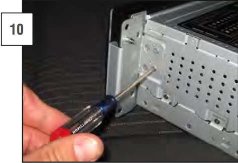
Attach the supplied mounting brackets to the new head unit.
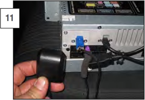
Mount any antennaes, cameras, etc. and run the wires through the vehicle; attach them to the rear of the new head unit, using the color coded diagram on top of the unit. Install the new head unit into the vehicle, making sure not to pinch any wires. Reinstall the dash pieces and test the head unit. Be sure to cover any electrical connections with electrical tape.
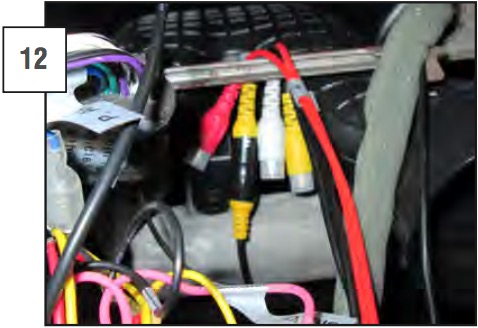
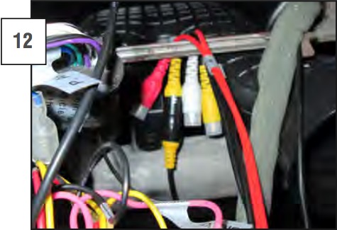
Attach the yellow “CAMERA” rca connection to the yellow rca connection that is on the the red ( ) / black (-) wire side of the camera intermediate harness. Connect the red wire to a 12V switched vehicle wire and the black wire to a vehicle ground wire. Run the intermediate wire through the vehicle to the camera’s mounting position, keeping it out of sight and away from moving or hot parts.
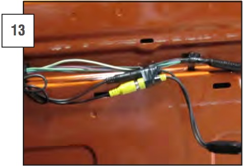
Attach the other end of the camera intermediate harness to the back up camera wiring as shown.

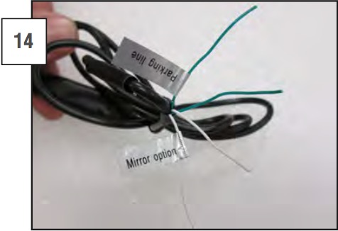
Depending on mount location of the camera and line preaferences, the wires may be left cut or they can be stripped and connected to either mirror the image or add parking lines.
IMAGE MIRROR OPTION: WHITE
1. Front Mount: connected
2. Rear Mount: cut
PARKING LINE DISPLAY OPTION: GREEN
1. Parking Lines Off: connected
2. Parking Lines On: cut
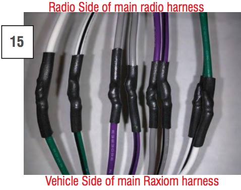
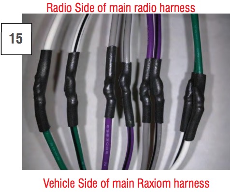
For vehicles equipped with premium audio, connect rear speaker outputs to front outputs and vice versa. All 8 (4 front and 4 rear) will need to be cut and reconnected.
New configuration will be as follows:
White to Green
Gray to Purple
Purple to Gray
Green to White
2011-2015 Wrangler Raxiom Navigation
Above is a diagram of the wires included with the head unit. The GPS Antennae With Wire (B), External Microphone With Wire (D) and Camera With Wire (F) should be mounted in their respective areas, then the wires should be routed to the head unit and connected.
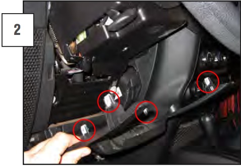
Remove the knee bolster by pulling down on the top of the panel. The panel is hinged on the bottom and it will swing down, once the (4) metal clips release.
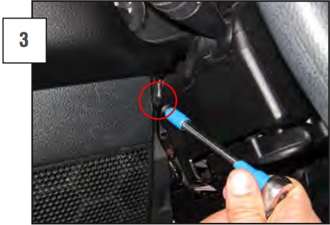
Remove the (2) 7mm screws; there is (1) on each side of the steering column.
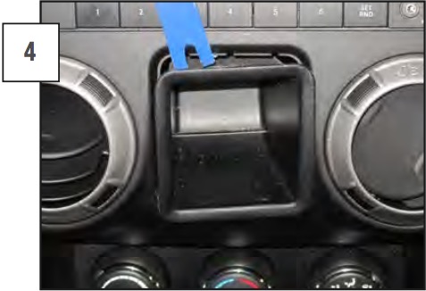
Remove the center storage container by prying the upper and lower tabs to release it from the radio bezel.
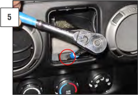
There is (1) 7mm mounting screw at the bottom of the open area left from removing the storage container. Remove the screw.
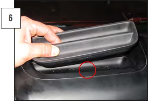
Remove the upper dashboard storage tray by lifting it by the center tab. There is (1) 7mm screw underneath the removable storage tray. Remove the mounting screw.
Pull the top of the dashboard away from the windshield. The upper metal clips will release, then pull the bottom and slide the upper dash piece up and out of the vehicle.
Remove the (4) radio head unit retaining screws from the stock head unit. There will be (2) on each side of the head unit.
The head unit can be pulled out of the dash. It will be tight at first, but it will release from the mount with some pressure. Unplug all wiring from the back of the stock head unit and remove it from the vehicle.
Attach the supplied mounting brackets to the new head unit.
Mount any antennaes, cameras, etc. and run the wires through the vehicle; attach them to the rear of the new head unit, using the color coded diagram on top of the unit. Install the new head unit into the vehicle, making sure not to pinch any wires. Reinstall the dash pieces and test the head unit. Be sure to cover any electrical connections with electrical tape.
Attach the yellow “CAMERA” rca connection to the yellow rca connection that is on the the red ( ) / black (-) wire side of the camera intermediate harness. Connect the red wire to a 12V switched vehicle wire and the black wire to a vehicle ground wire. Run the intermediate wire through the vehicle to the camera’s mounting position, keeping it out of sight and away from moving or hot parts.

Attach the other end of the camera intermediate harness to the back up camera wiring as shown.
Depending on mount location of the camera and line preferences, the wires may be left cut or they can be stripped and connected to either mirror the image or add parking lines.
IMAGE MIRROR OPTION: WHITE
1. Front Mount: connected
2. Rear Mount: cut
PARKING LINE DISPLAY OPTION: GREEN
1. Parking Lines Off: Connected
2. Parking Lines On: cut
For vehicles equipped with premium audio, connect rear speaker outputs to front outputs and vice versa. All 8 (4 front and 4 rear) will need to be cut and reconnected.
New configuration will be as follows:
White to Green
Gray to Purple
Purple to Gray
Green to White
